Mapping provides a spatial view of the distribution of archaeological entities on the excavation site.
Basic Principles
 It is important to understand the three points below:
- A topographic point (Topo point) is located using two values: latitude and longitude.
- Each form, photo, and drawing of the intervention can have one or multiple topo points.
- These topo points are displayed on the map and can form geometries (points, lines, polygons, circles) depending on their number and the selected configuration.
Map Module Interface
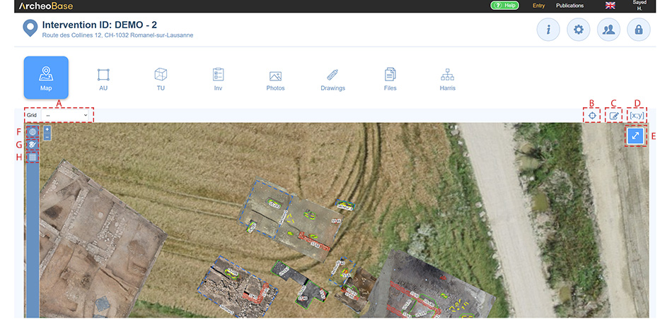
A: Grid
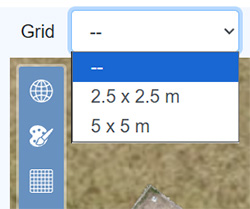
Grids with various resolutions can be selected from the dropdown menu. The displayed resolutions are those defined under H: Grid Configuration.
B: Centering the Map
The icon  automatically centers the map on the coordinates entered when the archaeological site or intervention was created.
C: Drawing Georeferenced Geometries
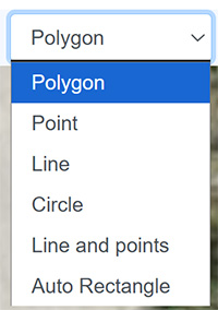
Georeferenced geometries can be drawn directly on the map. The icon  opens a dropdown menu with the different types of geometries.
D: Coordinates
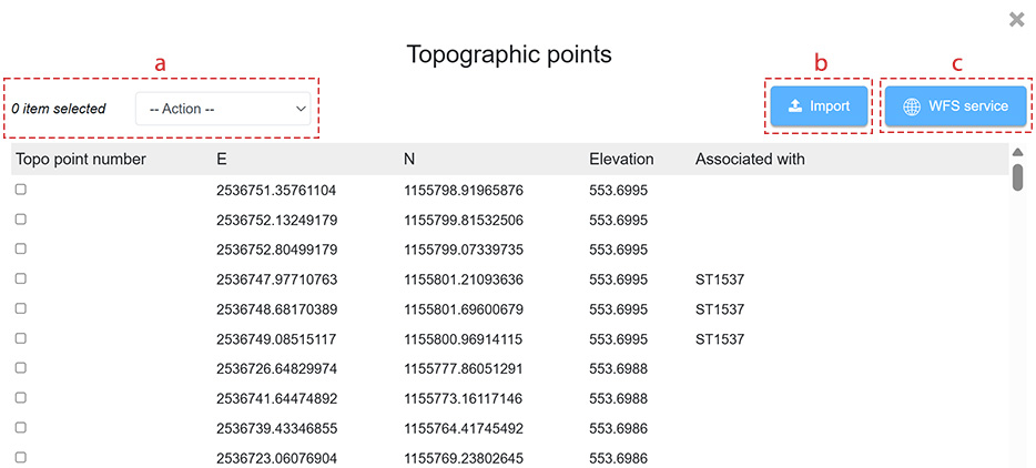
The icon  displays the full list of topo points for the intervention.
| a | Selected topo points can be deleted from this table. |
| b | The Import button allows importing a file with coordinates and matching them with existing forms. |
| c | The WFS Service facilitates exporting all coordinates related to a specific form type, such as US, to another program like QGIS. |
E: Full Screen
The icon  displays the map in full screen mode.
F: Map Elements
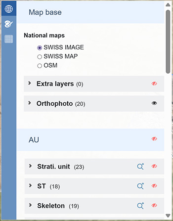
The icon  lists all elements of the site that have coordinates (Forms, Drawings, Photos, and unassigned topo points). Clicking on an element zooms in on it. Each element can be made visible or hidden from this menu.
G: Map Configuration
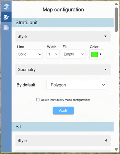
The appearance of map elements can be configured by activating the icon  . The Color, Fill, Line Thickness, Line Type, and the type of geometry formed by the topo points are all configurable.
H: Grid Configuration
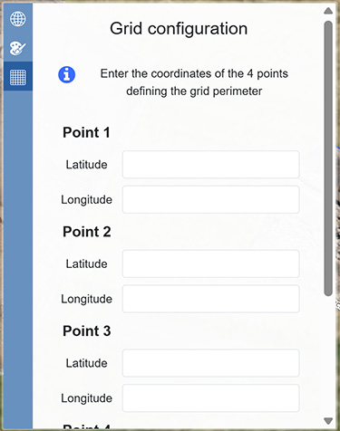
The icon  opens the configuration window for grid settings.
Measurement
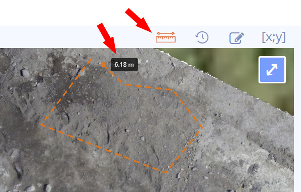
Distances and perimeters can be measured directly on the map. The tool can be activated by clicking on the measure distance button located at the top of the map. Measurements can now be made by left clicking on the map.
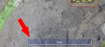
A dynamic distance scale is displayed at the bottom of the map.
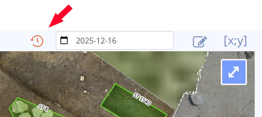
Map History
Changes to the map and coordinates are versioned and can be displayed by clicking on the clock icon and choosing the desired date in the calendar. This feature allows existing boundaries to be adjusted throughout the excavation process and makes it possible to revert to any previous version of their modifications.