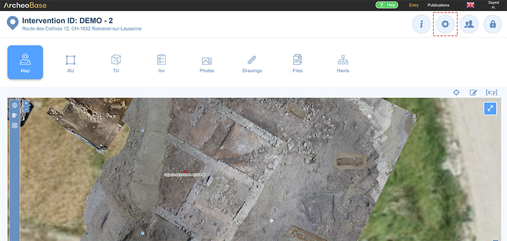
The coordinate system for each intervention can be configured from the configuration tab located above the main menu.
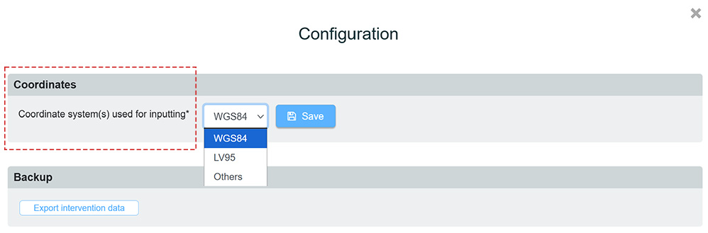
Next, select the coordinate system. All coordinate systems are supported. Please contact the support (support@archeobase.ch) if the desired coordinate systems isn't shown.
- Others
- Users may use other coordinate systems by defining the Proj.4 reference. This is useful to create a personalized coordinate system for the intervention.
Topo Point
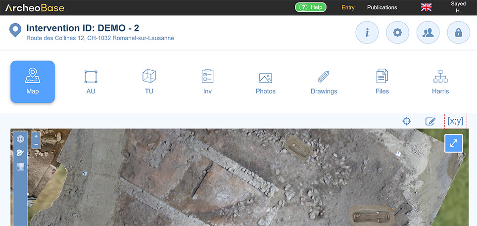
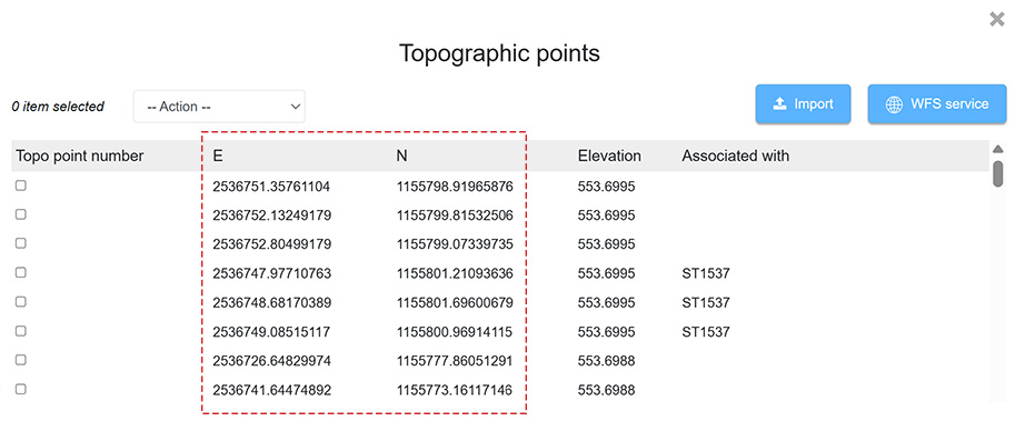
A Topo Point consists of the intersection of two coordinates, Longitude and Latitude. The list of Topo Points for an intervention can be accessed by clicking the icon  .
The following table of Topo Points shows that some Topo Points lack a Topo Point Number. In fact, the only required elements are the Latitude and Longitude coordinates. Assigning a number to a Topo Point is optional, as are altitude and association values.
Each form type, including Photo and Drawing, can have one or more Topo Points. These Topo Points are displayed on the map and can form different geometry types, depending on their number and chosen configuration.
Depending on the working method used, having a Topo Point number associated with the longitude and latitude can be useful. A practical example could be:
- In ArcheoBase, some forms reference only Topo Point numbers that were generated without coordinates.
- Field coordinate acquisition was recorded in an Excel file using the same Topo Point numbers but with longitude and latitude added.
- The coordinate import process using the Excel file automatically assigns coordinates to the Topo Points within ArcheoBase forms.
- The forms and their respective geometries then appear on the map.
Each form type, including Photo and Drawing, can have one or more Topo Points. By connecting these points, geometries can be created. The different geometry types are: polygon, point, line, circle, line and points, auto rectangle.
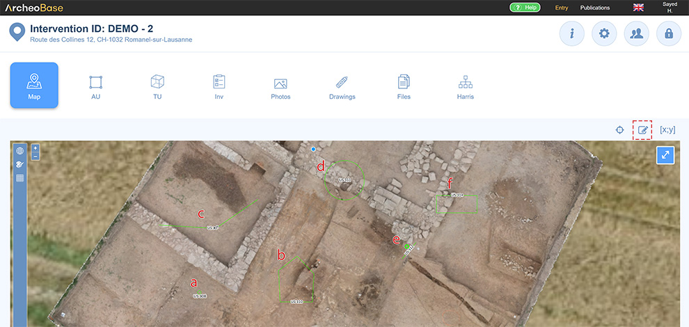
| a | Point Used when there is only one Topo Point or when the user does not want to link the Topo Points together. |
| b | Polygon Possible when there are at least three Topo Points. The first and last coordinates are connected. |
| c | Line Possible when there are at least two Topo Points. The first and last coordinates are not connected. |
| d |
Circle Each Topo Point is surrounded by a circle with a radius that can be defined in the configuration. |
| e | Line and points Creates a line between the first and last Topo Point. An additional point is automatically added beside the line, clockwise relative to the order of the Topo Points. This geometry is useful for representing section drawings, with the point indicating the drawing’s viewing direction. To change this point’s direction, refer to Section Orthophotos. |
| f | Auto rectangle Creates a rectangle of configurable width using the first and last Topo Point. This geometry is useful, for example, to represent a trench. Only two points are needed; the rectangle width is configurable and represents the width of the excavator’s bucket. |
Coordinate Insertion
Each form or media can be geolocated. Insertion of Topo Points or their constituent coordinates can be done in three different ways:
- Using Coordinates generated from the map
- Using Coordinates generated from a form
- By Importing a coordinate file
Automatic surface area calculation
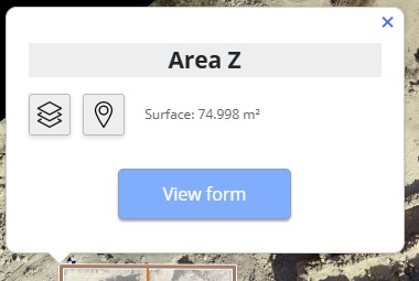
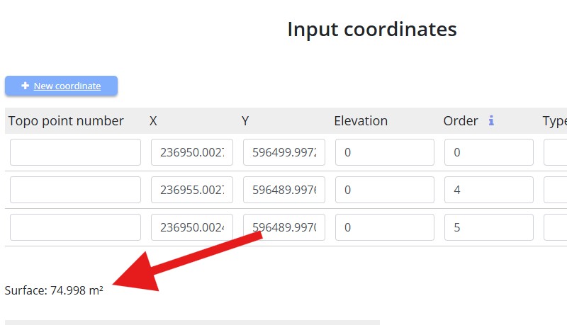
The surface area, expressed in square meters (m2), is automatically calculated for all forms that represent a polygon. This information is available in several locations:
1. In the popup displayed when clicking on the polygon on the map
2. On the form’s coordinates page
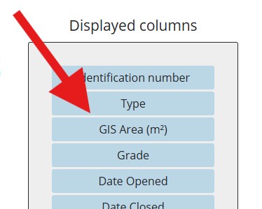
3. In the columns of the table listing the forms. The area can be displayed in the table by enabling the display of the column GIS Area (m2)